- #Resistor color code install#
- #Resistor color code software#
- #Resistor color code code#
- #Resistor color code download#
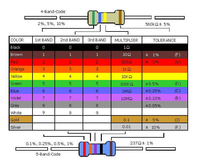
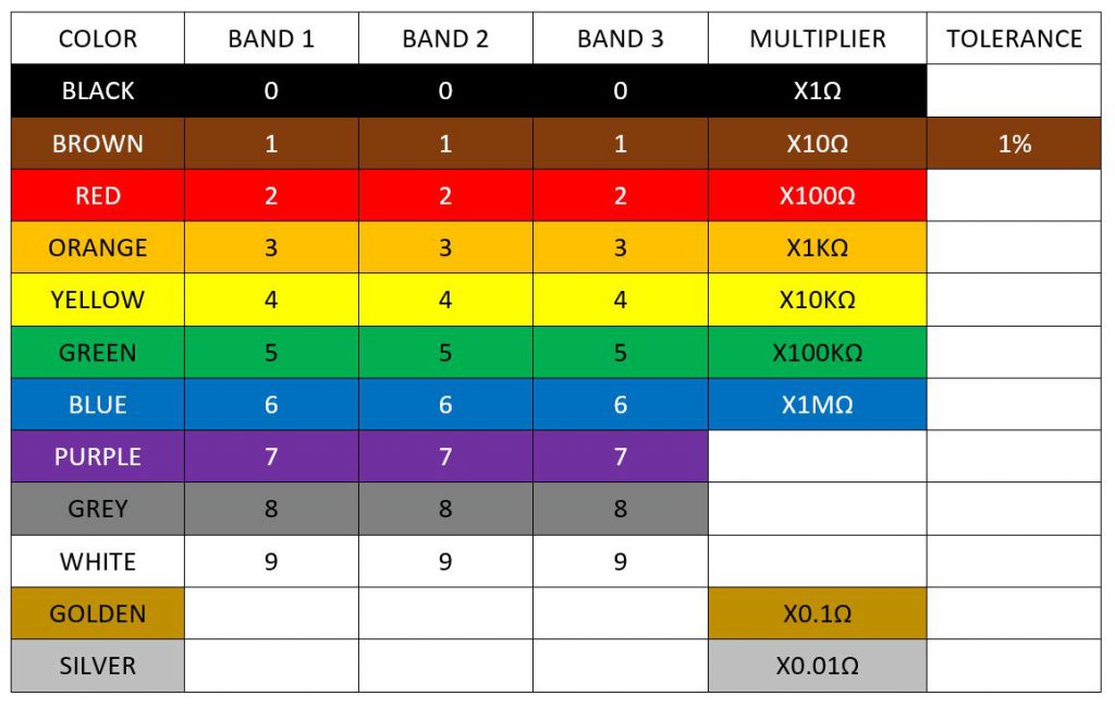
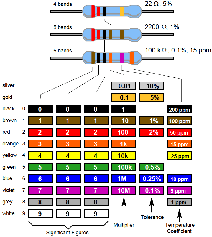
By matching the colour of the first band with its associated number in the digit column of the colour chart below the first digit is identified and this represents the first digit of the resistance value.
#Resistor color code code#
The resistor colour code markings are always read one band at a time starting from the left to the right, with the larger width tolerance band oriented to the right side indicating its tolerance. It consists of a set of individual coloured rings or bands in spectral order representing each digit of the resistors value. These coloured painted bands produce a system of identification generally known as a Resistors Colour Code.Īn international and universally accepted resistor colour code scheme was developed many years ago as a simple and quick way of identifying a resistors ohmic value no matter what its size or condition. So to overcome this, small resistors use coloured painted bands to indicate both their resistive value and their tolerance with the physical size of the resistor indicating its wattage rating. But when the resistor is small such as a 1/4 watt carbon or film type, these specifications must be shown in some other manner as the print would be too small to read. Then close all Arduino IDE software.The resistance value, tolerance, and wattage rating are generally printed onto the body of the resistor as numbers or letters when the resistors body is big enough to read the print, such as large power resistors. Check include library menu”, this indicates that your I2C LCD library installation has been successfully installed on the Arduino IDE software. Step 5 : Wait for the message “Library added to your libraries.
#Resistor color code install#
Step 3 : Install the I2C LCD library on the Arduino IDE by clicking on Step 2 : Click on the Arduino icon to open the Arduino IDE software.

#Resistor color code download#
Step 1 : Download the I2C LCD Library at
#Resistor color code software#
Installation of I2C LCD library on Arduino IDE software Check include library menu”, this indicates that your SevSeg library installation has been successfully installed on the Arduino IDE software. Step 4 : Select the Library file you downloaded earlier and Click Open to start the Library installation process. if ( multiplier_state > Include Library > Add. > Arduino code for the resistor color code and ohmmeter learning kit #include #include SevSeg sevseg LiquidCrystal_I2C lcd1 ( 0x27, 16, 2 ) LiquidCrystal_I2C lcd2 ( 0x3E, 16, 2 ) LiquidCrystal_I2C lcd3 ( 0x25, 16, 2 ) float max_number = 0 const int first_black = 14 const int first_brown = 15 const int first_red = 16. The Arduino Mega board will perform a resistor value calculation, and the LCD will display a resistor value such as the actual resistor value, the resistance tolerance value, the maximum resistance of the resistor, and the minimum value of the resistor. Then the seven segment display will display the value of the resistor color code. This circuit aims to receive input from the user to set the value of the resistor color code. This area is the area for the color code resistor circuit. The second area is the area other than the red box area. The range of options supported by this ohm meter is 0 Ohm to 2k Ohm, 2k Ohm to 20k Ohm, 20k Ohm to 200k Ohm, 200k Ohm to 1M ohm. By using the color code chart, one finds that green stands for 5 and blue for 6. In the example shown here, the 4 bands are green, blue, red and gold. These resistors have two bands for the resistance value, one multiplier and one tolerance band.

The user will select the appropriate ohm range and perform a resistor value check. The four band color code is the most common variation. This ohmmeter circuit is used to check the resistor value. The first area in the red box is the ohmmeter circuit.

The circuit above has been split into two areas. > Below are the tips for reading the resistor color code > Circuit connection << The 4-color resistor variant is the most commonly found and most widely sold. The resistance value available in the market has also been standardized, and this standardized value is called the preferred value. Each band or strip has different color values ranging from three to ten colors. Each band or strip has its value function, such as resistance value and tolerance value. Color codes are separated into bands or strips. Almost all of the lead type resistors are generated with the same color code. Resistance values can be translated by color code. > DOWNLOAD THE ARDUINO IDE VERSION 1.8.4 HERE > What is the resistor color code? << The code used in this writing may work or may not work with other versions of the Arduino IDE.

Intro : Resistor color code and ohmmeter learning kits are interactive kits that allow their users to enter the color code of the resistor, calculate the resistance value of the resistor, and finally, check the value of the resistor by using an ohmmeter.ĭifficulty Level: Medium, Has Arduino BasicsĬAUTION : The Arduino IDE version used for writing this tutorial is Arduino IDE Versi 1.8.4.


 0 kommentar(er)
